HAHN Automation Group Brings Vision Guidance to Laser Welding
Vision guidance is used in situations where the combination of tolerance stack-ups, beam diameter, and feature size would cause inconsistent welds. In this case study, you will read about how we have used our vision guided laser welding in a wide range of custom equipment for MedTech, Automotive, and Electronics industries.
#automation #MedTech #laser #welding #vision #Automotive #Electronics
- Increase weld consistency
- Allow inspection inline with welding process
- Reduce scrap and increase throughput
Challenge
With tight tolerances and complicated assembly processes, consistently laser welding complex components can be a difficult task to accomplish and maintain over a long period of time in a production environment.
The focused spot diameter for laser welding applications is typically 100-1,000 microns. The position of the joint under the laser must be precise enough to ensure that the focused spot does not miss. The allowable misalignment is a function of the focused beam diameter as well as the joint design and is typically in the range of ±75 microns.
For many applications, hard tooling is sufficient to locate the part for welding. However, in applications where part tolerances exceed ±75 microns, active positioning of the weld joint and/or laser spot are required for an accurate, consistent weld.
Developing a Solution
The HAHN Automation Group has integrated vision-guided laser welding systems into a wide range of custom equipment—including laser spot welders, seam welders, and laser machining centers—to solve complex welding problems for the MedTech, Automotive, and Electronics industries.
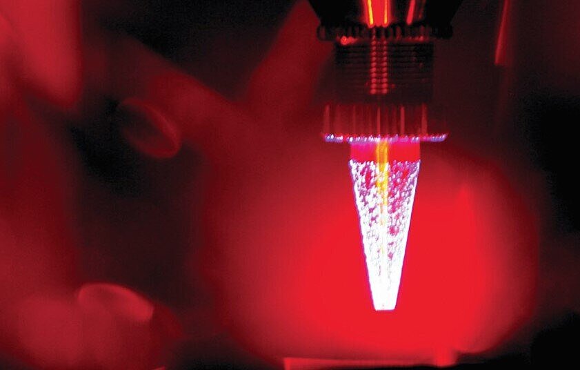
These photos below demonstrate the accuracy of a vision-guided laser weld as opposed to a traditional weld. In the first photo, the magenta line is the position of the weld seam. The yellow line is where a traditional laser welding system will place the weld seam. This would produce a rejected part. In the second photo, the system automatically aligns the laser path with the weld seam. The red welding target is now properly placed on the seam. The result is an approved part each time.